Because I described how my students and I used a bridge tester to prepare for scaling up our walking machine in my TrotBot post, I thought I should describe how to use a bridge tester safely, and how I built mine.
Overview
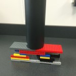
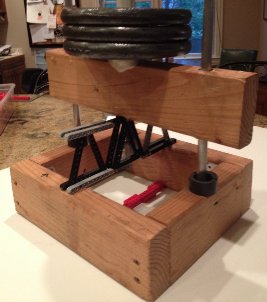
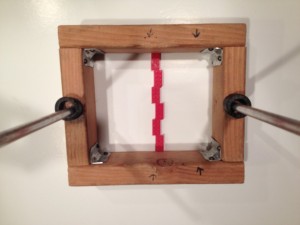
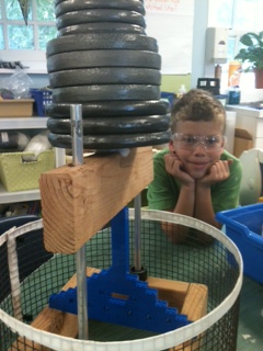
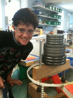
There are probably better, or simpler bridge testing methods for LEGO bridges than what I built, but this design has served its purpose. Testing bridges with it is pretty straightforward. The bridge is placed perpendicular to the weight-bearing 2×4, and plates are added until the bridge fails.
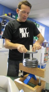
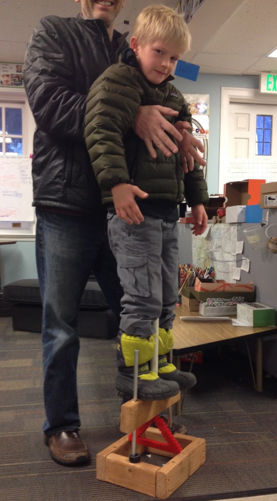
The 2×4 on which the weights are stacked slides up and down the vertical aluminum tubes. These tubes prevent the weights from falling off the tester, and they also allow younger students to get more excited about testing their creations by standing on their bridges (with me spotting them with their arms held down by their sides, and my arms under their arm pits so they only drop an inch if their bridges fail). This test only occurs if the bridge holds all the weight plates.
Safety considerations
Students and teachers should wear safety glasses when testing as parts can fly when bridges fail.
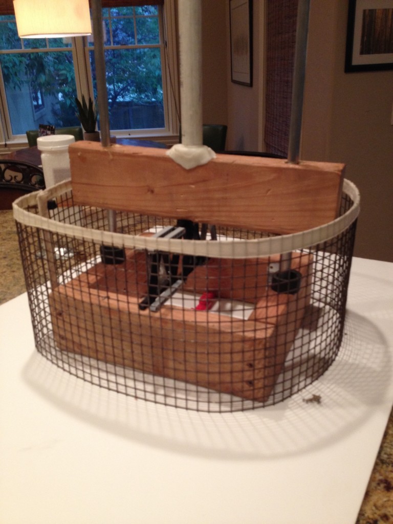
A safety screen helps to prevent parts from flying, and curious hands from getting hurt. My first version of the tester lacked a safety screen. Even though I would always caution students to avoid putting their hands near their bridges during testing, and performed the tests myself, students would often get so absorbed in their bridge’s performance that they would try to touch cracks that formed in their bridges while testing. To prevent this I added a wire mesh screen.
A side comment on testing truss bridges
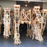
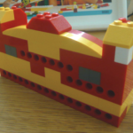
Below is an example truss bridge built with LEGO Technic beams. Notice the side-to-side symmetry, which is necessary to prevent bridges from twisting while under loads.
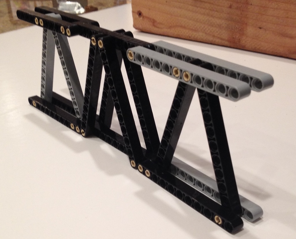
When testing truss bridges, it’s critical that the weight-bearing 2×4 rests on the vertex of a triangle, and not on a triangle’s side, otherwise the Technic beams will break. A triangle’s magical strength only exists at the corners!
Also ensure a vertex is in contact with both sides of the base.
Construction
The gap between the two sides of the base is 7.5 inches, or six bricks.
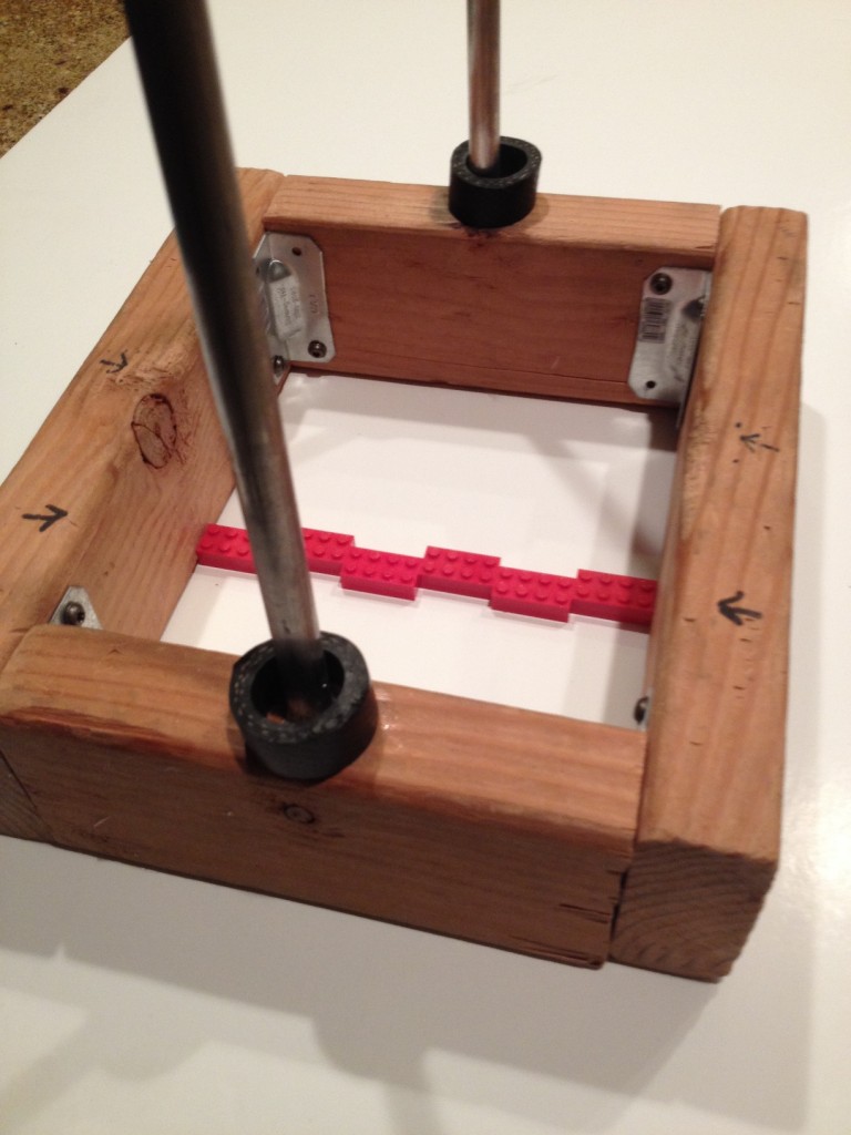
The aluminum tubes are 1/2 inch in outer diameter, and their holes in the base were drilled on a drill press so they would be vertical and parallel (drilled about half way through). First, drill holes in the below weight-bearing 2×4, and then use that as a template to drill the holes in the base to ensure the weight-bearing 2×4’s holes are lined up and don’t bind on the tubes.
Once one hole is drilled into the base put an aluminium tube through both holes to anchor one side of the weight-bearing 2×4 to the base before drilling the other side’s hole. Once both holes in the base are drilled the tubes can be fixed to the base with wood/metal epoxy applied to the tubes as they are inserted. Be sure to check that the tubes fit before applying the epoxy!
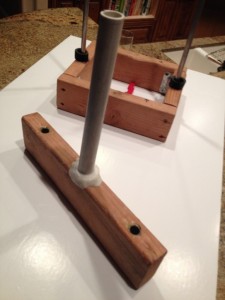
The PVC tube for the stacked weights is 1 inch in OD. After drilling a 1 inch hole in the weight-bearing 2×4 (only part way through) and ensuring the PVC tube fits in it, the tube was then fixed in place with “friendly plastic” (hot glue should work fine).
I also added brass bearings to the holes of the weight-bearing 2×4 to further prevent it from binding on the aluminum tubes (see below).
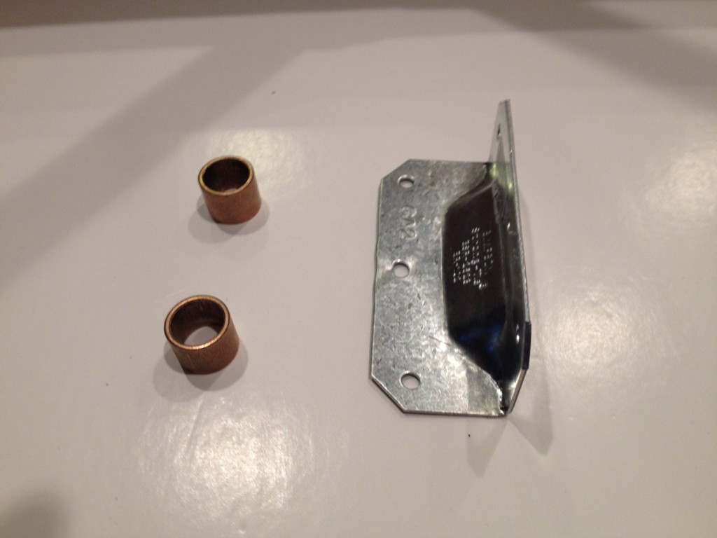
I used bearings with an ID of 9/16ths to provide a bit of play, which first required enlarging the drilled holes in the weight-bearing 2×4 with a bit size depending on the wall thickness of the bearing. After testing that the bearings fit into the holes, and that the weight-bearing 2×4 could still slide on the tubes without binding, I glued the bearings in place with wood/metal epoxy.
Latest posts by Wade (see all)
- Linkage Warm Ups 2: LEGO Jumpers and Hoppers - 28 May 2019
- Linkage Warm Ups 1: LEGO Punchers and the 4-Bar Linkage - 13 April 2019
- Rapidly Prototyping Strider – Smoother, Stronger, Faster - 30 August 2018
- How to build and safely use a bridge tester - 10 July 2015
- TrotBot Walking Machine - 5 July 2015