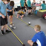
I’ve often wanted to see greater educational use of LEGO robots more in alignment with how robots get used in the real world – taking on that dull, dirty, dangerous, or distant task.
One approach could be to measure an area, map the features, and then conduct missions based on the calculated map. The idea sounds a bit challenging for a LEGO robot, but not if we take it in bite-sized pieces. Let’s start with measuring area while following a line.
If we can provide a frame of reference for the robot, then we can calculate how far we’ve gone in any direction with a little odometry and trigonometry.
The easiest frame of reference I found is to use a magnetic compass and set magnetic North to be the Y-axis on a cartesian coordinate system. I also assume the robot begins its travel from the origin: (0,0).
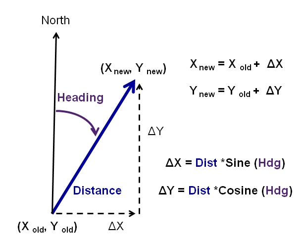
When the robot moves, the distance it travels becomes the hypotenuse of a right triangle whose legs are the North (y-axis) and East (x-axis) components. The new robot position can then be calculated by adding the North components (old y position + additional travel in the y direction) and the East components (old x position + additional travel in the x direction).
When written as equations, this becomes:
X new = X old + ΔX
Y new = Y old + ΔY
Where do the ΔX and ΔY come from? They come from multiplying the distance traveled and the sine or cosine of the robot’s heading. In equations:
ΔX = Dist *Sine (Hdg)
ΔY = Dist *Cosine (Hdg)
Programmers get to choose how far between each coordinate pair they want to let the robot travel before calculating the new (x,y) coordinate pair. In LEGO robots, that value usually comes from odometry based on wheel rotations.
Here’s a graphic summarizing the creation of new (x,y) coordinates for one leg of travel:
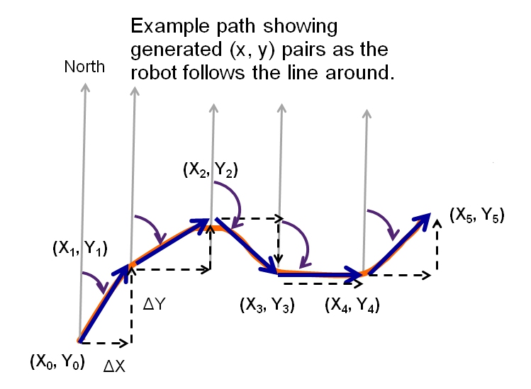
Here’s a graphic summarizing the creation of (x,y) coordinate pairs for five legs of robot travel along the line:
When doing this the first few times, it will probably be easier to write the (x,y) coordinate pairs to a file and then calculate the area off line, which I’ll explore next.
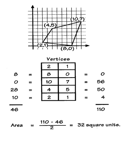
Calculating exact area from continuous curves perfectly usually requires double integrals. But our robot is converting the smooth boundary it’s following into a series of (x,y) coordinate pairs connected by straight lines. There’s a method to measure area within any polygon bounded by straight lines. Here it is:
- Beginning with any vertex, list the coordinates of the vertices in order, moving counter-clockwise around the polygon. List the first pair again at the end.
- Find the diagonal products from left to right.
- Find the diagonal products from right to left.
- Sum each column of products.
- Find their difference and divide by 2. This is the polygon’s area.
Here’s a graphic showing the approach:
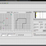
I’ve implemented the approach using a line following robot by writing the calculated (x,y) pairs to a data file and then bringing them into a spreadsheet for plotting and calculating.
Here’s a graphic showing the results:
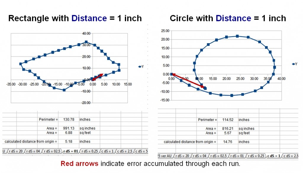
They’re not perfect, but should be good enough for most classroom applications. The red arrows indicate the difference between the origin / robot starting position and its endpoint. Both points at the tips of the red arrows are actually coincident and result (most likely) from odometry errors in the robot’s distance calculations.
Pitfalls
But what about South and West? Think of South as negative North and West as negative East.
Odometry errors. For most applications with LEGO robots, using the values LEGO provides on the side of the tire is probably sufficient. Similarly, a measured wheelbase from tire center to opposite tire’s center is usually sufficient. But, when we start into more precise measurements, those approximations become apparent as they introduce error. There are a couple of ways to reduce this error.
- Measure the size of the wheel / tire under the full weight of the robot and use that as the diameter value in the odometry calculations instead of the values LEGO provides on the side of the tire. (also referred to as scaling error)
- Develop correction factors for the effective wheelbase of the robot as described in the University of Michigan Benchmark test. This test uses a 4 meter square path, multiple times, clockwise and counterclockwise to measure errors and provide corrective data for the programmer.
Distance Choice. We need to choose a small enough distance between each set of new (x,y) calculations to make sure we don’t miss any significant features… but we also need to be mindful of our robot’s ability to store data and accurately calculate distance. Also, if our shape for measurement has long straight sides, it’s probably sufficient to calculate each new (x,y) pair less often than if we are working with a more complex shape. In the data plots above I used one inch of distance and the LEGO motorcycle wheels (design circumference = 10.09 inches) with no corrections.
If you’re up to the programming challenge, this can calculated during the robot’s travel so it arrives at the end point with the answer shown on screen. I hope to share an example in the relatively near future.
Further reading
- Area the Easy Way – the effort here was inspired by an activity in Fresno Pacific University’s Wilbert and Luetta Reimer’s book, Historical Connections in Mathematics Volume III , AIMS Education Foundation. Area the Easy Way (page 24) is a great example for calculating area without double integrals. Their graphic used by permission.
- UMBMark: Borenstein and Feng, UMBmark: A Benchmark Test for Measuring Odometry Errors in Mobile Robots, 1995, http://www-personal.umich.edu/~johannb/Papers/paper60.pdf Does a great job spelling out the different types of odometry errors and their effects on robot motion. Gives insight on how to correct.
- Green’s Theorem: Wikipedia: http://en.wikipedia.org/wiki/Green’s_theorem Provides background for line integrals about a closed curve and the measurement of the enclosed area.
- This post as a MS Word file
- Presentation file with more details.
Latest posts by Craig (see all)
- NXT exercises – One approach - 2 February 2016
- Why I like educational robots - 18 November 2013
- Area Measurement: Follow the Path - 27 May 2013
- Program structure – simulating publish and subscribe - 25 May 2013
- Pendulum mathematics - 25 May 2013