 Unlike normal GPS units, commonly found in smartphones or your car, that are accurate to roughly three meters, differential GPS uses two GPS receivers to get a reported accuracy of three centimeters! That’s a little over an inch! If this holds true, differential GPS could be used for a range of high precision applications.
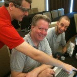
This summer, a fellow rising senior and I had the task of characterizing the error of a differential GPS unit. In the case of our project, we would like to use differential GPS for hexacopter-based radar.
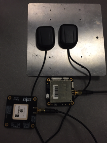
For radar on a hexacopter to be successful, we need to know the precise location of the copter at all times during flight. Any errors in location can cause immense blurring in the radar image and make it indecipherable. Because of this, we need to understand the exact distribution of position errors that we can expect from our differential GPS unit. For our project, we used the commercially available Piksi, made by the San Francisco based SwiftNav. Even though the Piksi’s error distribution looks great on paper, there is a chance that this unit will not stand up to the requirements of our project; the standard deviation of its distance error must be no more than 1.75cm.
So, on to testing! We needed to design a testing rig that can pull the GPS unit at a constant rate without interfering with its satellite signal. Simply pulling the receiver by hand was ruled out early. Aside from the impossible task of freely pulling the receiver at a constant speed in a straight line, we lost our signal any time my hand came near the receiver. Not great. Testing by hand also had one other problem: we had no reliable way to raise or lower the GPS unit to test the vertical error distribution.
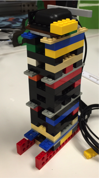 That got us thinking of possible construction materials for a sled that is stable, convenient to pull, and variable in height. The answer was obvious: LEGO bricks. The Tufts Center for Engineering Education and Outreach (CEEO) was gracious enough to lend us all of the bricks that we needed. With them, we designed the sled you see at left.
Notice the LEGO Technic pieces used as runners. The holes in those pieces allowed for a string to be thread through them, giving us a mechanism to pull the sled. The body of the sled itself is built in two-inch sections that can easily be added or removed to alter the height of the GPS unit.
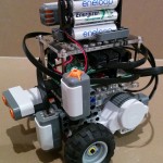
Now that we had our LEGO sled, we needed a way to pull it at a constant rate. Since pulling by hand is shaky at best, we looked at robotic solutions, the Arduino in particular. With it, we built a bot with two motors that could pull the sled forwards or backwards at the press of a button.
This was our final result:
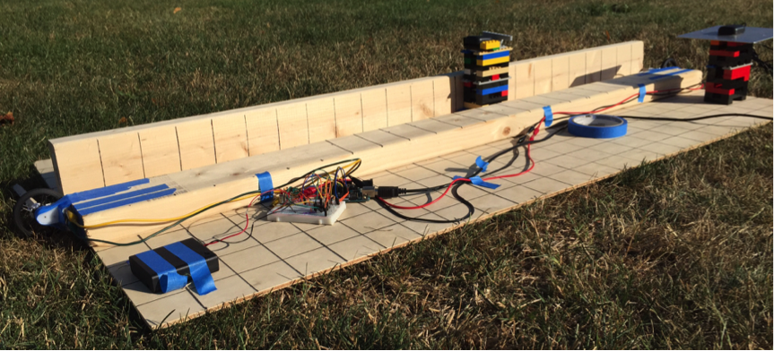
Fun to build? Absolutely. Over engineered? Probably. Effective for testing GPS accuracy? Yes!
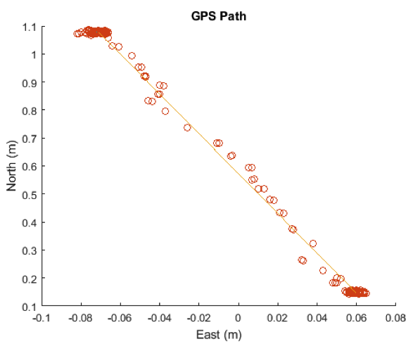 Here is a sample of the results that we got from pulling the GPS with our testing rig. The orange line shows the actual path that the GPS unit followed, which is linearly interpolated from the starting and ending points. Each orange circle then represents the logged GPS location. A quick glance at the data shows the pinpoint accuracy of the GPS. We can see that most logged locations are no more than 1cm away from the line. Delving deeper, we discover that the GPS error in each direction resembles a normal curve distribution, while the error in line distance forms a Rayleigh distribution. The Rayleigh distribution is formed from normal distributions of its components, in our case the X, Y, and Z-axes. This gives us confirmation that our collected data is coherent and valid.
Now, down to the numbers. Our aggregate standard deviation in the Y-direction is 0.51cm and 0.71cm in the Z-direction. Further testing is required to determine the standard deviation for the X-direction, but we have reason to believe that it will be similar to that of the Y. So when we combine the numbers that we do have, the total standard deviation of error from the line is 0.65cm. Almost a full centimeter lower than our maximum allowed error!
We still need to complete several more rounds of testing. This will allow us to determine the X distribution of our GPS error and determine a more accurate value for the total distance error. This value will increase slightly, but I do not think it will increase beyond our standard deviation threshold of 1.5cm.
There are two main takeaways from the GPS testing that we did this summer. First, our differential GPS is accurate to around 0.65cm. This accuracy falls well within the requirements for our hexacopter based radar system; we can be confident that positional errors from the GPS will not distort our radar data. Second, and this is the real biggie, any test is made infinitely more exciting when LEGO is involved.
Special thanks to Ethan Danahy and the Tufts CEEO for lending us the LEGO bricks for our testing!
Ian Fletcher
CEEO
Latest posts by CEEO (see all)
- Chair for Mr Bear - 21 August 2020
- Assistive Technology: Making Lives Easier - 20 August 2020
- Sturdy Tower - 14 June 2020
- Going the Distance - 21 May 2020
- GPS accuracy testing with LEGO bricks - 10 September 2015